

OEM Waterproof Connector Selection Tips for Harsh Environment Reliability
2026-11-19
Most waterproof connector failures do not start with a low IP rating. They start with a choice that looked right on the datasheet but ignored how heat, vibration, moisture, and cleaning chemicals act together in the field. For OEM engineers, that gap is expensive. This guide cuts through the usual spec-sheet noise and focuses on practical selection factors that improve harsh environment reliability. Along the way, we’ll point to proven approaches from REUNION to help you make connections that last.
Read the Environment Before You Read the Datasheet
Most datasheet parameters are answers to questions nobody asked in your specific circuit. A part that looks fast on page three can fall apart when the rail has 200 mV of switching noise, the load is more capacitive than the test fixture, and the ground return shares a via with a gate driver. Spend time mapping what the board actually presents to the pin before trusting any curve.
Temperature is another place where the environment quietly rewrites the numbers. The thermal resistance figures assume a certain copper area, airflow, and board thickness, yet the same package on a crowded four-layer board may run twenty degrees hotter. If you do not know where the heat is coming from and how it leaves the area, reading a maximum junction temperature is just arithmetic with a guessed input.
A practical habit is to write down the real operating boundaries first: input common-mode range, output load transients, supply tolerance, ambient temperature, and nearby switching fields. Then look for those conditions in the datasheet footnotes and test circuits. You will often find that the headline number belongs to a cleaner bench setup, and the part you need is the one that still behaves in your environment.
IP Ratings Are Only the Starting Line
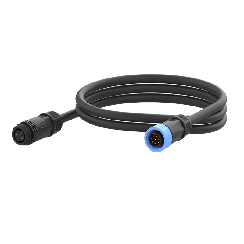
An IP rating tells you how well a device shrugs off dust and water under controlled lab conditions. But those tests don't account for the way real life beats on gear. Humidity inside a pocket, salt spray near the coast, or the slow weakening of seals after months of thermal cycling all behave differently than a thirty-minute dunk in fresh water. So while the digits matter, they're a snapshot, not a promise.
What often gets overlooked is that the rating applies to a brand-new unit. Rubber gaskets harden, tiny abrasions accumulate, and a port cover left slightly ajar on a windy day invites trouble. Users who rely solely on the specification tend to skip basic care, assuming the enclosure will always perform at its factory peak. In practice, the lifespan of protection depends as much on maintenance and environment as it does on the original certification.
A more useful approach is to treat the rating as a baseline filter, then look at the build choices behind it. Are the seals replaceable? Is the port design forgiving when cables get yanked at odd angles? Does the coating on internal boards resist corrosion beyond what the ingress tests measure? Those answers separate gear that merely passes a benchmark from gear that keeps working in places where weather and accidents write the real spec.
Match Materials to Chemicals and Temperature Swings
Material compatibility charts rarely tell the whole story once thermal cycling enters the picture. A seal that holds up in a static compatibility test can fail after a few dozen swings between -20°F and 180°F simply because the elastomer stiffens, shrinks, or takes a compression set. Rather than relying on general chemical resistance tables, it pays to test candidate materials under the actual temperature range they will see, including the speed of the swing.
For aggressive solvents and acids, fluoropolymers like PTFE and modified PTFE tend to handle both chemical attack and broad temperature ranges, but their cold-flow behavior can leave gaps in flanges unless the design accounts for creep. Metals need equal scrutiny: stainless steel works for many caustic streams, yet chloride-bearing chemicals at elevated temperatures can trigger stress corrosion cracking even when the same alloy survives at room temperature.
Elastomers require a different kind of matching. EPDM holds up well against hot water and many polar solvents but falls apart in petroleum-based fluids. FKM compounds offer better oil resistance, though low-temperature flexibility drops off unless you choose a specialty grade. A useful approach is to shortlist materials by chemical class first, then cut the list based on the lowest and highest expected surface temperature, then run a physical test with the exact concentration and thermal cycle rather than assuming a generic rating will transfer.
Look at Contact Stability Under Vibration and Thermal Load
In real operating environments, a contact interface rarely fails from a single clean cause. Vibration and thermal cycling interact in ways that static testing misses. Small relative motion between mating surfaces can scrub away oxides and expose fresh metal, which sounds helpful until that same motion begins accumulating wear debris and creating intermittent opens. At the same time, temperature swings alter the physical preload because housing, fastener, and spring materials expand at different rates. The practical result is not a simple derating curve; contact force can drop below the threshold needed to maintain gas-tight asperity contact under dynamic load.
A useful evaluation goes beyond milliohm readings at room temperature. It tracks resistance while the assembly is swept through vibration profiles and thermal cycles together, with short interruptions sampled at high speed. Many connector systems show a recognizable signature: resistance spikes appear only when vibration coincides with the hot soak, because thermal expansion has already relaxed the normal force. If vibration is tested cold and thermal soak is tested static, the worst combination slips through unnoticed.
Practical design changes usually target the mechanical loop rather than the contact material alone. Adding compliance in the beam, reducing mass overhang, matching CTE between housing and board, and specifying a lubricant that stays put through thermal excursions all help keep the contact point stable. It is also worth confirming whether the contact finish can tolerate micro-motion without building insulating layers. Stability under combined loading is less about peak spring force and more about keeping that force predictable across temperature and vibration extremes.
Make the Cable Exit Part of the Waterproof Envelope
Treat the cable penetration as a sealing surface from the start, not as a hole that gets plugged after assembly. Most water enters where the outer jacket ends and individual conductors continue to the board, so the goal is to keep the jacket intact as far into the housing as practical. A cable gland with a matched grommet works well when the enclosure wall is flat and the gland compresses against the jacket, but adding a short length of adhesive-lined heat shrink just before the gland gives water a much harder path to wick through. If the wall is thin or curved, a bulkhead fitting with an external rubber boot tends to hold up better than a standard nut-and-grommet seal because it spreads the clamping force over more of the cable surface.
For designs that face frequent submersion or strong temperature swings, move the seal away from the connector pins and toward the raw cable. Potting the back of a bulkhead connector with a flexible compound can stop water that gets past the outer seal, provided the wires are fanned enough for the compound to flow between them. Leave a service loop inside the enclosure so condensation drips off the lowest point of the loop instead of running toward the exit. A stainless steel compression plate over a soft rubber gasket often outlasts a single grommet because it maintains steady pressure as the rubber ages and the housing expands and contracts.
Test the Mated Pair in Your Own Worst-Case Setup
The only way to know if a mated pair will hold up in your application is to put it through the exact conditions you dread. Bench tests with clean, steady signals rarely expose the real weaknesses. Instead, run the pair at your lowest expected supply voltage while driving the maximum capacitive load you can imagine, then cycle the temperature between your coldest cold-soak and hottest heat-soak. Watch for any hint of latch-up or duty-cycle distortion that never shows up on a typical datasheet curve.
Pay attention to layout details you normally ignore. Long, thin traces between the driver and receiver add inductance that can turn a clean edge into a ringing mess. If your setup forces the pair to share a return path with a noisy switching regulator, don't assume isolation will save you. Probe the differential lines right at the receiver pins, not back at the connector, and look for the specific failure signature you have seen in the field, not some generic eye diagram.
Finally, swap in multiple units from the same reel and from different lots. Marginal pairs often pass by luck once, then fail when a slightly faster or slower part takes its place. Push the pair until it breaks once, then back off enough to find the true margin. That number, measured in your own worst-case setup, is worth far more than any guaranteed specification.
FAQ
IP67 handles temporary immersion, while IP69K is built for high-temperature, high-pressure spray downs. If the equipment gets cleaned with steam or aggressive jets, IP69K matters more than a higher immersion rating.
Both, but chemical compatibility usually decides first. Nylon may survive dry heat but swell or crack around certain oils, coolants, or cleaning agents, while PBT or metal can hold up where nylon fails.
That area sees constant bending, pulling, and thermal movement. Look for overmolded strain relief, a long flexible boot, and a cable clamp that grips the jacket instead of just the wires. Also keep cable bend radius well beyond the connector rear.
Not necessarily. High cycle ratings often come from lighter contact materials or spring designs that wear well on a bench but may not survive corrosion, vibration, or wide temperature swings. Match the cycle rating to the actual service life instead of chasing the highest number.
They create the actual environmental barrier, and they age. A connector can look fine externally while the seal has hardened or taken a set. Replace O-rings and face seals whenever the connector is opened for service, and use the recommended lubricant instead of random grease.
Because lab tests rarely combine thermal shock, vibration, chemical spray, and UV exposure the way a machine sees them. Small gaps open when materials expand and contract at different rates, or when cables pull sideways during operation. Ask for validation that includes combined stress, not just a static IP dunk.
Very important, especially at the micro level. Gold over nickel works well for low-voltage signals, but tin can handle higher current if forces stay stable. In damp conditions with temperature swings, fretting corrosion can attack tin contacts faster than many people expect.
The lock must hold up under vibration and still be easy to release with gloves or frozen fingers. Look for a positive latch you can feel or hear, and avoid designs where the locking tab is exposed and likely to get snagged or broken during maintenance.
Conclusion
OEM teams often treat connector selection as a datasheet comparison, but harsh environment reliability starts long before checking an IP code. The actual mounting location matters more than the brochure: a connector near spray washdown, direct sunlight, hydraulic fluid, or repeated thermal shock will fail differently than a bench test suggests. IP ratings are useful only as a baseline because they describe static submersion or spray conditions, not the real combination of pressure pulses, condensation, and vibration that a mating pair sees in service. Material choice has to line up with specific chemical exposure and temperature swings; a seal that handles water spray may swell or crack when it meets coolant, oil, or cleaning agents, and a housing that survives cold may become brittle after repeated hot-cold cycling. Selection should therefore be driven by the surrounding environment first, with datasheet ratings used as a filter rather than a final answer.
Contact stability under vibration and thermal load is another area where cheap connectors fall short. Look for solid retention features, stable normal force, and enough wipe or anti-fretting design to keep resistance low when the system is moving or heating unevenly. The cable exit deserves equal attention because it is part of the waterproof envelope, not an afterthought: strain relief, sealing grommets, and cable jacket compatibility have to work together or water will track along the conductors. Finally, nothing replaces testing the actual mated pair in your own worst-case setup—mount it as it will be installed, add thermal cycling, spray, mechanical shock, and real cable routing, then monitor for intermittent contact or leakage. A connector that passes in a clean lab often reveals weak points within a few hours of this kind of abuse, and that early signal is what protects field reliability.
Contact Us
Contact Person: Hayley Liang
Email: [email protected]
Tel/WhatsApp: +86 13480625451
Website: https://www.reunion-china.com/